 |
|
|
|
|---|---|
|
|
|
Overview: |
|
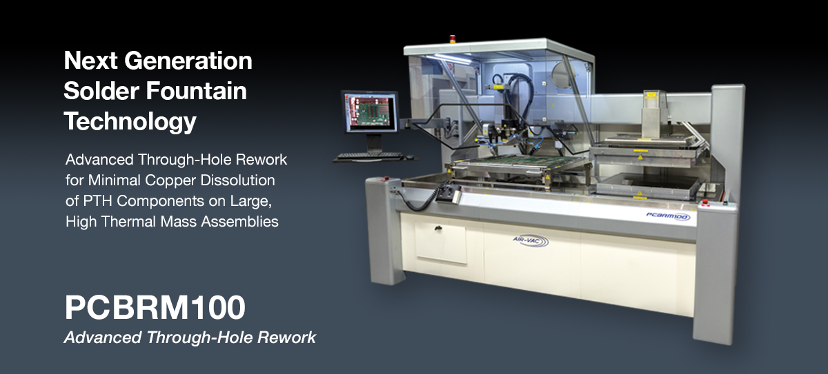
Next Generation Solder Fountain Technology Key Features/Benefits:
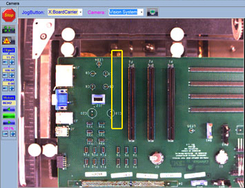
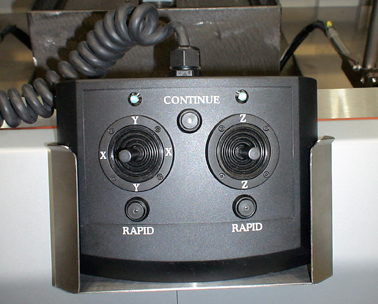
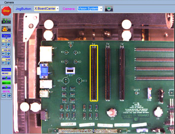
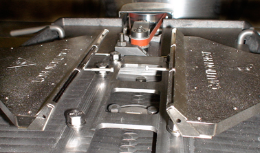
The EZ-Line alignment system features a down-looking digital camera with zoom lens mounted on a programmable "Y" axis that superimposes the image of the solder stack over the top of the board (figure 3). X/Y joystick-based controls (figure 4) are used to quickly and accurately align the component with the solder stack (figure 5). The desired rework position can be taught on-the-fly or stored in the program.
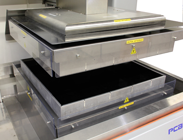
A 28" x 28" quartz composite top and bottom IR preheater (16Kw) with 25 watts per square inch heating density and independent temperature control provides rapid, uniform preheating of even the largest, most thermally challenging PCB's. The preheater panels have an extremely high radiant efficiency and do not depend on external reflectors. The top preheater panel has s programmable "Z" axis which allows the preheater to "sandwich" the PCB based on its topside topography, thereby creating a high-efficiency oven-like preheating effect (figure 6). A thermocouple attached to the PCB provides temperature-based preheating control for process repeatability.
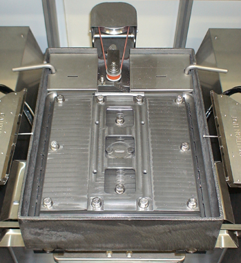
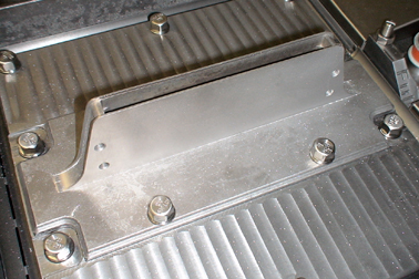
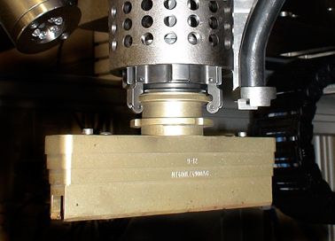
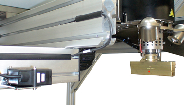
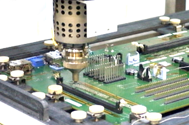
The heart of the PCBRM100 is a cast iron solder pot with titanium pump components (figure 7). No coatings of any kind are used to handle the aggressive nature of lead-free solder alloys. The pot has a solder capacity of 90 pounds and is nitrogen inerted. An internal chambering system along with a servo-motor driven pump creates a laminar solder flow with extreme thermal uniformity across the wave (+/-2˚C). Quick change titanium solder stacks direct a flow of solder against the lead pattern of the component to be reworked (figure 8). The solder pot is programmable in the "Y" axis and has quick electrical disconnects so that the existing pot can be removed and replaced by a spare pot with a different solder alloy.
|
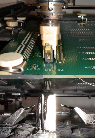
A typical removal process would be to preheat the entire board to 150˚C followed by a Focused Convective Heating (FCH) stage (figure 12) until all joints reach approximately 200˚C (as per the thermal profile) at which time the bottom side pins are immersed in solder for 10-20 seconds depending on the thermal mass of the component and PCB. Top and bottom side focused convective heating continues during solder immersion. Solder contact combined with FCH provides the maximum thermal transfer in the shortest possible time. The nozzle lifts automatically and the operator removes the component. This hybrid heating approach eliminates the requirement for 100% convective/IR heating as is done on BGA rework machines which reduces potential issues such as exceeding the maximum package temperature specifications, resin recession and board discoloration.
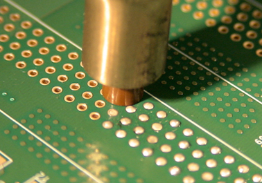
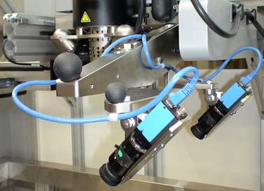
The PTH barrels can be cleaned immediately after the component is removed and the solder flow stops. The PCB remains in place over the solder stack with the bottom convective heating blades on. The component nozzle is replaced by the barrel cleaning nozzle (figure 13) which provides heat and vacuum to remove the solder in the barrels. The vacuum tip is made of a high temperature composite to prevent any abrasion of the pads or laminate (figure 14). A precision force sensor controls the initial touch off of the vacuum tip on the board. A vacuum sensor automatically and continuously adjusts the tip height providing non-contact barrel cleaning. Dual digital cameras provide the operator with multiple viewing angles during the cleaning process (figure 15).
The replacement process typically duplicates the removal process where FCH occurs until the joints reach 200˚C at which time the bottom side leads are immersed in solder. However, instead of the nozzle lifting and the operator removing the component, the nozzle remains in place over the component while it is soldered in place. Using FCH in this fasion eliminates the solder contact time typically required to bring the component through an extended soak stage during both the removal and replacement processes. The reduction in solder contact time results in reduced copper dissolution. In addition, topside FCH during the replacement process improves barrel fill by providing a heated upward path for the solder to flow. Specifications Facility Requirements
|
|